Overview
Projects and macros can be parameterized, making it easy to reuse them or embed them within other projects and macros. You can:
-
Define named parameters for any project or macro.
-
Use parameters to reconfigure tools or to add and remove tools dynamically.
-
Use property configuration controls to build dialog boxes with multiple inputs and variables.
-
Embed projects or macros in other projects or automations by dragging them from the repository onto the containing project's canvas.
Defined parameters can be independently set for each embedded project or macro. You could, for example, create a project that operates on data for a specific U.S. state, define the "state" setting as a project property, and then embed multiple instances of the project, each running on a different state.
That projects and macros run in a single process with any embedded projects and macros. If you nest many complex projects or macros you may run out of memory resources. Use the Management Dashboard to monitor memory usage.
Configure project parameters
Use Data Management's project parameters editor to define user-settable parameters and global variables, and build a user interface to solicit a variety of information from the user.
To configure project parameters:
-
Open a project or macro, and then select Parameters on the Project menu. You can also right-click the project canvas, and then select Project parameters.
-
Go to the Parameters tab on the Properties pane.
-
Add controls:
-
To add a new control to the list in the left pane, select the create new icon

-
To add controls for all project input and output fields, select

-
To remove a control, select the control and select

-
To change the order or controls, use the


-
-
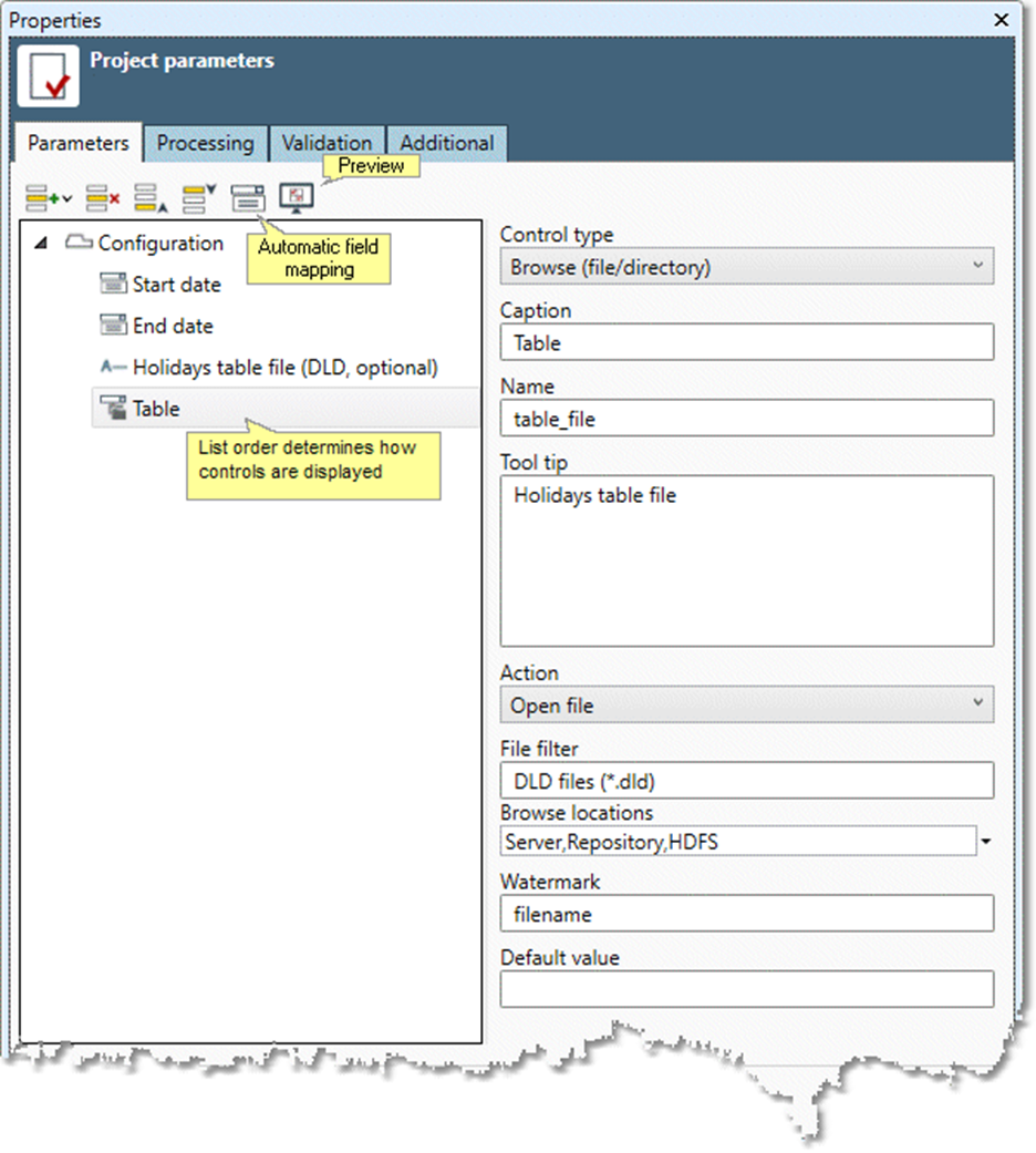
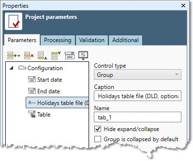
Select a control and then configure options in the editor section:
-
Control type is the user interface element used to collect configuration information from the user on the Properties pane. All control types can be assigned a Name and configured to function as a dynamic interface. Most can also be assigned a Caption and Default value. Depending on the type selected,

-
|
Type |
Function |
Additional options |
|---|---|---|
|
|
Organizes and labels user interface elements. |
None. |
|
|
User clicks browse button on file selection tool to perform Action. |
Action: one of Open file, Save file, or Select folder. File filter: filter string containing a description of the filter, followed by the vertical bar (
Browse locations: restricts the locations that can be browsed to those selected: Server, Resource, Repository, Resource maps, and Local. Watermark: explanatory background text. |
|
|
Boolean: if selected, assigns |
Triggers. See Building dynamic interfaces. |
|
|
User selects a single value from a list of values or optionally enters text value. |
Edit mode: select Allow user typed variables to permit user-defined values or Allow values in list only to limit values to list items. |
|
|
User selects date from calendar control. |
None. |
|
|
User selects date and time from calendar control. |
None. |
|
|
Primarily useful for macros. User selects the Input name from which the table schema will be obtained. This matches the Input label in the Macro Input Proxy tool. The table schema contains the list of available input fields from which the user can select. Implicit default value is Input. |
Select Required to require the user to set the parameter. If your project has more than one input connector tool, specify Input name as the name of the input connector from which the field is to be chosen. |
|
|
Organizes and labels user interface elements. |
None. |
|
|
Organizes and labels user interface elements. |
None. |
|
|
User selects an integer value. |
Minimum value | Maximum value: the minimum and maximum values user can enter. |
|
|
Primarily useful for macros. Maps new fields produced by the project onto output field names. This matches the Output label in the |
Select Required to require the user to set the parameter. Select Always create on output if you want the field to be created on output, even if it does not exist on the input connection. This makes it easy to set up with logic like "If the user-specified field exists on input, use it and alter its value on output. Otherwise make a new field that the macro alters and makes available on output." |
|
|
User enters a password, which is masked. |
None. |
|
|
User enters simple text. |
Maximum length: maximum number of characters user can enter. Watermark: explanatory background text. Disable white space warning: prevents Data Management from showing a warning when user enters a leading or trailing space character. |
|
|
User enters arbitrary text. |
None. |
|
|
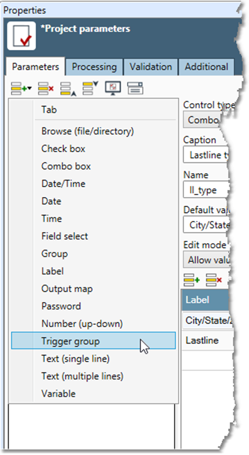
Defines group of controls targeted by defined Triggers. See Using trigger groups in dynamic interfaces. |
None. |
|
|
User clicks browse button on file selection tool to perform Action. |
Action: one of Open file, Save file, or Select folder. File wildcard: restricts the files displayed in the file browser to those matching pattern |
|
|
User selects time from calendar control. |
None. |
|
|
Defines a global variable. |
Data type. |
-
Caption is the property label the user will see in the project's configuration dialog.
-
Name is the name of the parameter. Use any string containing, letters, numbers, or the underscore character (
_). -
Tool tip is text displayed on rollover.
-
Default value is the initial value displayed by the control. Optional.
-
-
Repeat steps 3-4 to add additional user interface elements.
-
Select

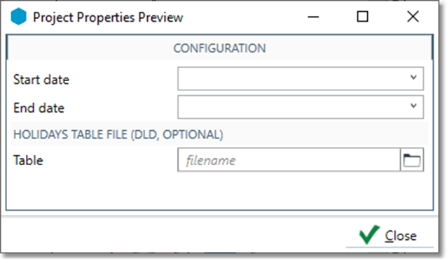
-
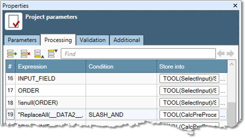
Go to the Processing tab to define how the user-settable parameters are processed. Each row in the processing grid defines a step in customizing the project's configuration to accommodate the user's settings. Within each row you specify three pieces of information:
-
Expression: defines the user-settable parameters as variables. The expressions can use any of the operations or functions defined in Data Management, just as you would use them in the Calculate or Filter tools. You can define multiple parameters in a single expression, as long as all parameters exist under the the
PARAMETERSpath in the configuration hierarchy. This is typically done when one macro wants to relay an entire set of its parameters to an "inner helper" macro that has the same parameters. This syntax is:-
Expression:
{ param1, param2, ... } -
Store into:
TOOL(toolpattern)/PARAMETERS
-
-
Condition: under which Expression will be applied to the configuration. If you leave this blank, then the expression will always be applied. Use conditions to control the circumstances under which a project is changed. For example, you might only apply a change if a certain field exists on the input.
-
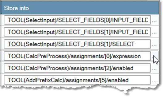
Store into: defines the part of the project configuration to change. Select the

-
-
Optionally, go to the Validation tab to define how to check the results of Expressions computed using the user-settable parameters.
-
A project's internal tools will generate errors if something is wrong. However, since the user of an embedded project cannot necessarily see what's going on inside the project, these error messages can be confusing. To prevent problems, you can specify validation steps for the project.
-
Each validation step checks the result of an expression computed using the user-settable parameters. If the validation expression produces the expected value, the project is configured correctly. However, if the validation expression produces an incorrect value, the project is misconfigured, and the associated Message will be displayed. Any validation error will cause the embedded project to be highlighted in red and the "parent" project will not run. Metadata functions such as $exists are particularly useful for validating input.
-
-
Optionally, go to the Additional tab to specify an icon for the macro or project. Select Load image, and then browse to any
png,jpg, orbmpformat file. Data Management will convert its format and crop it to 32 x 32 pixels. The icon will identify the project when it is embedded in a Data Management project window. -
Optionally, if you are changing a macro that is in use by other Data Management users, select Use Migration on the Additional tab. See Migrating macros for details.
Automatic field mapping
The Macro Input tool has an Automatic field mapping option. If enabled, this uses the available schema definition to map input data to macro processes. In the Macro Output tool, the Automatic field mapping option "undoes" any input mapping and restores the original field names.
When defining project parameters for a macro, you can use the ![]()
To define macro parameters using automatic field mapping:
-
Open a macro, and then select Parameters on the Project menu. You can also right-click the project canvas, and then select Project parameters.
-
Select the Parameters tab on the Properties pane, and then select

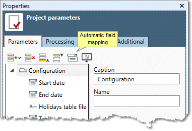
-
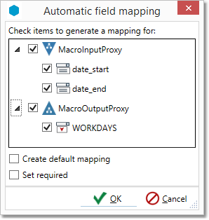
On the Automatic field mapping window, select the items to map. If the output schema is the same as the input, automatic field mapping may be unavailable for the Macro Output tool.
-
Optionally, select Create default mapping to set the default value of each item to the name of the associated input or output field.
-
Optionally, select Set required to require the user to enter a value for each input or output field.
-
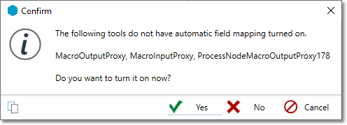
If you have not already enabled automatic field mapping on the Macro Input and Macro Output tool's properties, you will be asked to confirm.
-
Select Yes, and then configure project parameters as desired.
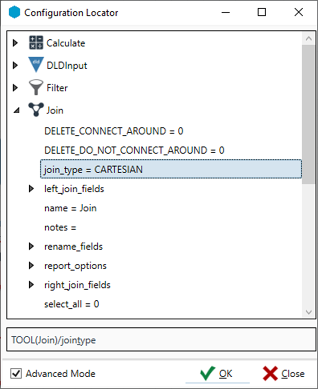
Configuration Locator
When configuring project parameters, you can view a project's user-configurable properties in the Configuration Locator, accessed from the Processing tab.
To view the Configuration Locator:
-
Open the Project parameters pane and select the Processing tab.
-
Select a box in the Store into column, and then select the

The configuration tree for the macro is displayed in the Configuration Locator.
Tool names
When you select an item in the configuration tree, the Store into field is filled with something like this:
TOOL(CalcPreProcess)/ASSIGNMENTS[0]/EXPRESSION
The TOOL(CalcPreProcess) portion of the configuration locator specifies which tool to configure. In this example, CalcPreProcess is the name assigned to a tool. In the Configuration Locator shown above, the tool names are displayed at the top-level of the configuration hierarchy. To uniquely specify tools within a macro, you should assign them easily identifiable names. You can specify tool names on the Execution tab of each tool's Properties pane.
Conditionally removing parts of a project
Sometimes you want to conditionally remove (or "prune") parts of a project or macro depending on the user's specification or the available input fields. For example:
-
You want to develop a project or macro where the user can use a check box in the configuration dialog to specify whether to standardize the address before processing. In this example, if the user elects not to standardize, you want to delete the address-standardization tool from the macro, and connect around the missing tool to continue processing.
-
You are developing a matching project or macro where multiple match passes are performed on the input. You want the user to be able to specify which kinds of matching to perform. In this example, for any match kind that the user chooses to omit, you want to delete the appropriate matching tools, and not connect around the missing tools (because each matching pass is a separate path).
These two kinds of macro configuration "pruning" are represented by the special configuration items DELETE_CONNECT_AROUND and DELETE_DO_NOT_CONNECT_AROUND.
To conditionally remove a portion of a macro:
-
Set
DELETE_CONNECT_AROUNDorDELETE_DO_NOT_CONNECT_AROUNDto a Boolean value equal toTrue(1) for the tool(s) you want to conditionally disable. Setting these toFalse, or not setting them at all (by using the Condition of a processing step) leaves the tools intact.-
Use
DELETE_CONNECT_AROUNDin cases where a conditional processing step is performed that produces an output table schema that is an augmented version of the input table schema. Tools that do this include Sort, Filter, Standardize Address, and Select. You can only use this on tools that accept a single input and generate a single output. -
Use
DELETE_DO_NOT_CONNECT_AROUNDin cases where a conditional processing step is performed that produces an output table schema that is nothing like the input table schema. Tools that do this include Window Compare, Pair To Group, and Create Tokens. -
Use
DELETE_DO_NOT_CONNECT_AROUNDin cases where a conditional processing step is performed that is a totally separate branch which doesn't get reconnected to a main data flow. For example, you might have a processing step that summarizes the data and produces an output report table. In this case you simply want to remove the tools entirely.
-
For more detailed information on these topics, see Programming Data Management.
Using wildcards in the configuration locator
If you want to operate on more than one item at a time in the configuration locator, you can specify a wildcard to cause it to match more than one tool. For example: TOOL('MyTool'.*)/DELETE_DO_NOT_CONNECT_AROUND.
Dynamic interfaces
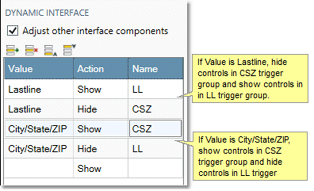
Dynamic interfaces change based on values selected by the user, typically showing/hiding or enabling/disabling controls in response to user input. For example, in the macro AO Address Quality, the field selection controls shown in the Lastline section change depending the value of the Lastline type parameter.
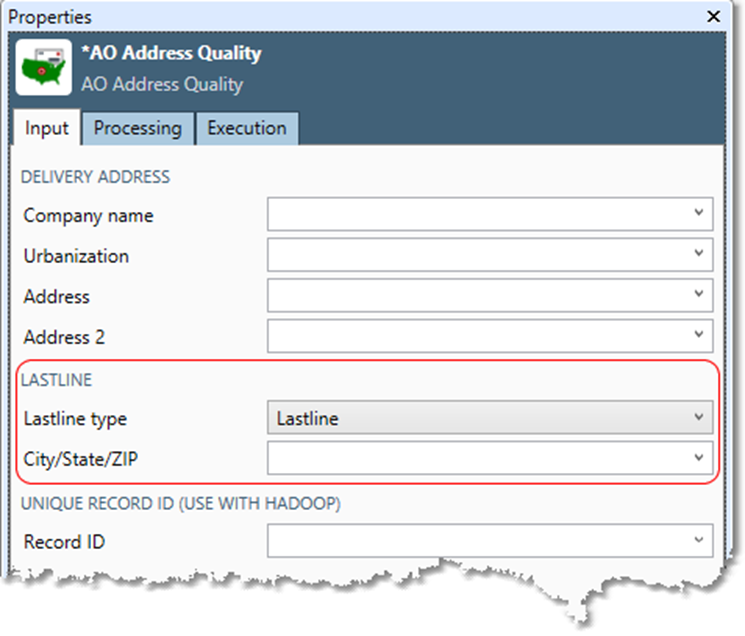
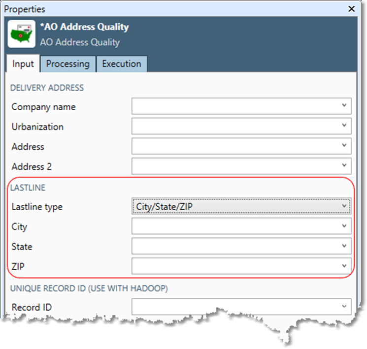
To achieve this effect, the Lastline type parameter is defined as a combo box with two possible values: City/State/ZIP and Lastline, and the Adjust other interface components option is selected and configured.
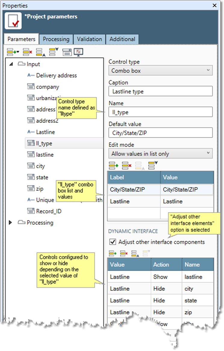
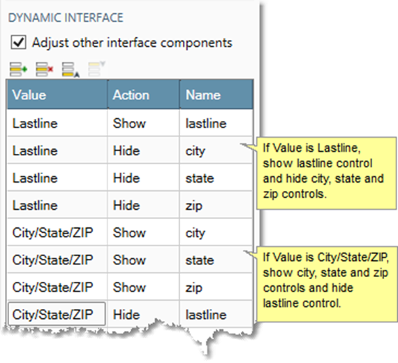
If the value Lastline is selected, Data Management hides city, state, and zip controls and shows the lastline control. If the value City/StateZIP is selected, Data Management hides the lastline control and shows the city, state, and zip controls.
You can also achieve the same dynamic effect by defining trigger groups.
Trigger groups in dynamic interfaces
If you have multiple controls that you want to show/hide or enable/disable in response to user input, you can use trigger group controls to streamline the process and organize your control groups. For example, in the macro AO Address Quality, the field selection controls shown in the Lastline section change depending the value selected in the Lastline type combo box.

Instead of defining the response of each control, we can add trigger group controls for the two possible values of the Lastline type combo box (CSZ and LL).
By dragging and dropping the city, state, zip, and lastline controls onto the CSZ and LL Trigger group controls, we define two trigger groups.
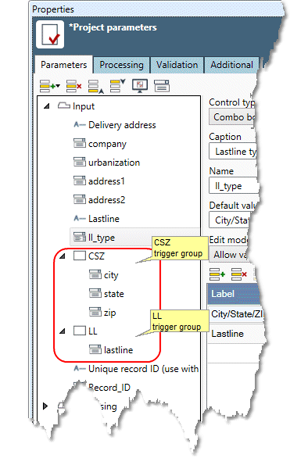
These trigger groups can then be used to define the dynamic interface.