

Overview
An automation consists of a set of steps, possibly connected to each other with control-flow connections or staging connections. Each automation step defines a discrete action or control logic.
When an automation is started, each step that has no input connections is triggered, and these execute. These steps in turn signal any downstream control-flow connections, causing later steps to trigger.
Most steps have two control-flow output connectors, success and error. When the step encounters an error, it signals output connections on the error output. When a step finishes execution normally (without error), that step signals the links attached to the success connector.
Each step has a control-flow input connector to which one or more control-flow connections can be connected from upstream steps. When every connection on a step's input connector is signaled, the step is triggered and becomes active.
A step can have any number of output and input connections.
Control flow connections
In automations, control flow connections convey activation information between steps. Each step generally has a single trigger input, and success (green) and error (red) outputs. The Branch step has multiple outputs, only one of which is signaled depending on the logic in the Branch tool.
In addition to the unsignaled and signaled states, a control-flow connection can also have a skipped state. The skipped state will cause all downstream steps to be skipped, and cascade the skipped state all the way down the control-flow graph. Skipped states are propagated as follows:
-
When a step succeeds, the success connections (if any) are signaled and the error connections (if any) are set to skipped state.
-
When a step that has an error connection fails, the error connection is signaled and the success connections (if any) are set to skipped state.
-
When a step that has no error connection fails, the step fails and no connections are set to any state.
-
The Branch step signals the chosen branch connection(s) and sets all non-chosen branch connections to skipped state.
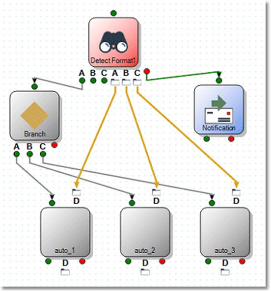
In the automation project shown below, the Detect Format step detected an error, signaling the Notification step and skipping all other processing.
While you may also manually configure a step with the Skip option on the Execution tab, the behavior of a step that is explicitly configured as “skip” is different than that of a step which is skipped because of control-flow. In particular, the downstream steps are not skipped. Instead, the skipped step is ignored completely while downstream steps continue to execute. This behavior may lead to unexpected or inconsistent results. We recommend that you do not deploy automations containing steps manually configured to skip in production environments.
Staging connections
Staging automatically links data files between automation steps. While regular Data Management projects stream record data between tools, automations use staging files to transfer data between steps. This allows any automation step to be restarted, since the staging data is persistent. Staging files are DLD format and normally written to the server-defined temp space. You can change the location of an automation's staging files by defining automation settings.
A step that supports staging input displays a file folder icon for each input at the top edge of the step. A step that supports staging output will display a file folder icon at the bottom edge for each output. You can connect staging inputs and outputs providing that no loops are created and the staging connections do not cross group boundaries.
Some steps support staging
Certain steps only display staging connectors when configured to use them.
-
Detect Format: every defined format with a Staging output specified creates a corresponding staging output connector on the step.
-
File System: the List files action creates a staging output connector.
-
FTP: an FTP step containing a
dircommand creates a staging output connector. -
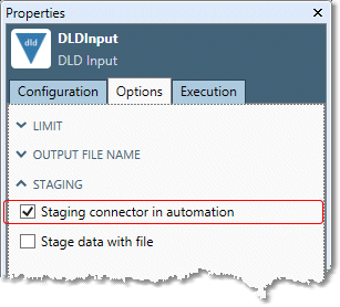
Project: any DLD Input tool in a project can be configured to be a staging input connector, and any DLD Output tool can be configured to be a staging output connector. You can prevent a specific DLD Input or DLD Output tool from being a staging connector by clearing its Staging connector in automation option.
-
Reader: the Reader step has a staging output.
-
Review: the Stage mode creates staging input and output connectors.
-
Writer: the Writer step has a staging input.
All groups support staging
Within a Simple group, you can drag the staging inputs of embedded steps to the file icon on the group's top border. This creates a corresponding staging input connector on the "outside" of the group so you can link to steps external to the group. Similarly, any staging outputs of an embedded step can be dragged to the file icon on the group's bottom border.
Within a While group or For Each group, staging inputs can be linked to the group boundary, but staging outputs cannot.
Staging and control flow
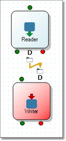
Normally control flow and staging connections follow the same routes. If you have a staging connection between two steps, there must also be a control connection. The following automation shows an error, because the Writer step has no control-flow input connected.
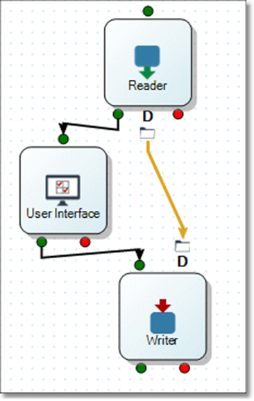
Staging connections need not always be exactly parallel to control flow connections. For example, you might want to pause execution waiting for user input between steps that have also have staging connections.
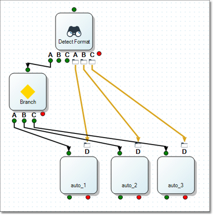
You can connect the control-flow output of a Detect Format step to a Branch, which then connects to (and selects one of) multiple downstream steps. Meanwhile, Detect Format's staging output connects directly to each of the downstream steps, bypassing the Branch.
Change staging methods
Changing staging methods can help you debug the projects in an automation by instantly re-specifying all of the staging connections in an automation.
Recall that projects used in automations become staging connections when you select the Staging connector in automation option in the DLD Input and DLD Output tools.
By default, Data Management automatically manages temporary files used for staging, rather than using the files named in the DLD tools. This allows more than one instance of the automation to run without contention for the staging files. However, this can be inconvenient when you are debugging an automation and its embedded projects, because the file names used for staging differ from the ones defined in a project. If you open a project, you don't see the data currently used by the automation.
The Stage data with file and Use named file for staging options in the DLD Input and DLD Output tools address this issue by causing automations to use the files named in the tools as the staging files. Normally, you would need to manually ensure that the files used by the connected DLD Output tools of the "producer" project and the corresponding DLD Input tools of the "consumer" project are identical. To make this easier, use Change staging method to adjust all of the staging files (and the DLD Output and DLD Input tools in the projects involved in staging) in one batch operation.
To change staging methods:
-
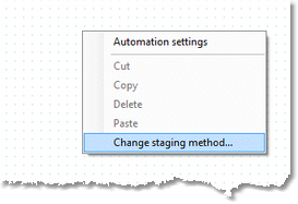
Right-click an automation canvas and choose Change staging method.
-
Select the desired operation from the Change staging to list:
-
Temporary files. Clears the Use named file for staging option in every DLD Output and DLD Input tool used for staging in every project in the automation. Choose this option if you want to run more than one instance of the automation at once. Do not choose this option if you want to open and debug projects in the middle of an automation run, and see the staging data in the project.
-
Named files (as currently defined in the DLD Output tools). Selects the Use named file for staging option in every DLD Input tool and DLD Output tool that is a staging connector, and alters the paths of the input tools to match the connected output tools. This lets you open and debug projects that are run within the automation and see the staging data in use by the automation. Choose this option if you want the staging files to go exactly where you've defined them in the projects.
-
Do not choose this option if you want to run more than one instance of the automation; there will be file conflicts.
-
-
Named files (make all new names in a defined folder). Selects the Use named file for staging option in every DLD Input tool and DLD Output tool that is a staging connector, and configures DLD Output and DLD Input tools to use newly-synthesized file names in the designated folder. This lets you open and debug projects that are run within the automation and see the staging data in use by the automation. Choose this option if you want the staging files to all go to the same folder; this helps to unify and centralize the staging data used by a collection of projects.
-
Do not choose this option if you want to run more than one instance of the automation; there will be file conflicts.
-
-
-
If you selected Named files (make all new names in a defined folder), specify the desired folder.
-
Select Preview to show the list of actions (changing projects and connections) that will be performed. Select Perform Action to execute these actions.
Automation logging
Like other Data Management projects, automation projects generate a log. Automation logs collate all of the contained project messages, warnings, and errors. Each log entry indicates the source of the entry with a path of the form A/B/C/D, where each component is the name of the nesting level.